|
Controller Configuration, Monitoring, and Control > Navigating the Interface > Summary Panel
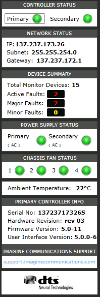
Summary Panel
The Summary Panel appears on the right side of the SEL-MCP3 Controller screen. It is for informational purposes, and provides alarm and status overview information for the frame as a whole at a glance. It is visible when the Dashboard, Fault Log and Streaming tabs are active, but not when the Configuration tab is active.
Summary Panel Contents
Item
|
Function
|
Controller Status
|
- Primary: Indicates presence (bright green), absence (dull green), or failure (red) of the controller module.
- Secondary: Indicates presence (bright green), absence (dull green), or failure (red) of the primary controller module. A secondary controller is recommended, but not required.
|
Network Status
|
|
Device Summary
|
Lists the number of devices, and the total number of alarms currently existing for the frame.
- Total Monitor Devices: The modules, including the frame device, that are contained in the frame.
- Active faults: The total number of faults currently active on all devices in the frame.
- Major faults: The number of active faults with severity 6-10.
- Minor faults: The number of active faults with severity 1-5.
|
Power Supply Status
|
The indicator for each installed power supply in the frame has the following meanings:
- Green: Power supply is present and functioning
- Dull Green: Power supply is not expected, and not functioning
- Red: Power supply is expected (based on the setting for the Power Supply Expected parameter), but is not functioning
The type of power supply (AC or DC) is indicated in parentheses for each power supply that is present.
The secondary power supply is optional, though recommended. If two power supplies are installed, when looking at the front of the frame, the primary power supply is on the left, and the secondary power supply is on the right.
|
Chassis Fan Status
|
There is an indicator for each fan in the frame (fans are required). The indicator displays red for each fan that has failed. When looking at the front of the frame, fan 1 is on the left, and fan 4 is on the right.
|
Chassis Temperature
|
Indicates the ambient temperature around the frame.
|
Primary Controller Info
|
Lists information for the controller.
- Serial No: This is the frame’s unique ID.
- Hardware Revision: Indicates the hardware revision of the controller module
- Firmware Revision: Indicates the version number of the controller firmware
- User Interface Version: Indicates the version number of the external control software on the controller module
|
To view the history of faults, see Faults and Events .
|

 Print
Print